Author Archives: Boat Nut

PSS Shaft Seal Bellows compression made easy

I recently replaced a PSS shaft seal on my new to me boat (Freedom 45). The shaft log area does not have good “two hands” access due to a water heater sitting on top (can’t be seen in the photo). Very good access with one hand at a time. I was pondering how I could do the bellows compression step safely with one hand. I figured the opposite of a standard ratcheting clamp would be perfect but all of the clamps I had my collection did not seem reversible without destroying them.

I started browsing around and found the DeWalt line of ratcheting clamps are designed to be reversible with a simple screw lock on the end. I picked one up and it worked perfectly. This PSS install was done completely with one hand. I marked the initial position of the rotor with a sharpie. Tightened the clamp until I had the required 3/4″ of compression then leisurely inserted the set screws to lock it. A spare zinc then provides a backup against rotor slippage (not in position yet in the photo). I believe this was the 12″ version of clamp. I liked the reversibility so much I added a few sizes to my tool collection. If your shaft log is hard to reach then this a perfect no stress way of getting the required compression.

Autopilot Install Finish

They say better late then never and here it goes.

It has been over two years since I finished the Autopilot install and I couldn’t be happier. The Simrad AC12 steers the boat beautifully and has made cruising a breeze.  Last year we did a two week cruise to Maine with some long delivery days where we barely touched the helm.

My last entry on the install showed completion of the rudder position sensor.  After the sensor was installed the next step was to get into the wiring.  Using NMEA2000/Simnet on the compass and the rudder sensor simplified the wiring.

The RC42 compass was installed low in the boat, under a settee close to mast.  Basically as close to the center of balance as possible.  This gives the RC42 a truthful picture of how the boat is moving without exaggerations that can cause overcorrections.

I installed the AC12 and wiring hub in the port lazarette on the aftmost bulkhead.  This simplified the wiring as it is just a few feet from the drive and NMEA2000 drops from the rudder sensor, helm mounted chart plotter and Simrad Gs25 mounted on the stern rail.  The AP24 was mounted in an existing pod at the binnacle.  It replaced an old Raymarine st4000 head with a similar cutout size.  I used the old wiring coming out to fish the new wiring coming in.  Using Simnet it was a single wire run.  I also reused the power line from the St4000 as well which speeded up the new wiring install.  The boat already had a dedicated breaker on the main electrical panel for an AP.

I have had a few comments asking for more photos of the sensor and drive install.  I will try not to disappoint with what is below.  I want to grab a few videos of the AP in action.


Sabre 36 Shower Support and Cabin Sole Repair (Part 2)

After the demolition was complete I let the area dry out for about a month.  I ran a boat Caframo Air Dryer right in the hole.  The strength of the stick built cabin sole is amazing.  I could walk around the unsupported area with little flexing.

I could feel a challenge coming up.  The sole curves up from the center and the existing floor thickness is variable from top to bottom due to the filler.  There is no way to simply lay in a single piece and have it easily align on all sides.  I decided to build it back up in many pieces. There is also the issue of how to match the coloring and grain.  I decided to take it one step at a time and see how things materialized.

IMG_2049

I had to come up with a way of supporting the new underlayment and bonding with the existing floor.  I decided to make some brackets out of 1/4″ G10 epoxy board and bond them to the existing sole.  I used 1/2″ Meranti ply to make a new shower support.  I decided to double it to improve rigidity.  I templated the new support before cutting and sealed it with a few coats of straight west system.

1/4" G10 epoxy board brackets to support sub-floor

1/4″ G10 epoxy board brackets to support sub-floor


Fitting new shower support

Fitting new shower support

After the new support was fitted and brackets installed, I templated using a piece of 3/16″ luan ply and transferred to the Meranti 1/2″.  To deal with clamping and curvature I drilled and tapped 10-24 holes in the G10 for mechanical fastening.  For fastening into the mast support beam I reused the 1.5″ slotted wood screws that came out during demolition.  Note that I filled all the old screw holes with west in an epoxy syringe.  I also did some drill samples in the beam and step to make sure there was no water damage inside.  Everything looked pretty dry.

I used epoxy on the brackets, shower support and subfloor edges (not where it is attached to the beam).  This will allow the patch to be removed if I ever opt for a complete sole replacement in the future.

Patch installed.  Edges were sealed with two coats of epoxy.

Subfloor patch installed. Edges were sealed with two coats of epoxy. Things looking better already.

After I fastened the ply I cut a slot in the center and inserted a small piece of ply as a center support.  The piece was epoxied to the hull underneath.  I also epoxied in the new shower support and screwed the subfloor to it.

IMG_2055

Poor shot of new shower support with thickened epoxy seal. This will be covered with cloth later.


Below Decks Autopilot DIY Part 5 (of many)

Sorry for the delay but now time to finish this.

With the hole drilled for the arm bolt and the drive mounted the next step is the rudder position sensor (Simrad RF25 NMEA 2000 sensor).  I scoured the net for reference photos and saw a few where the position sensor arm used the steering quadrant as an attachment point.  After an hour study in the aft lazarette I could see no way to make that work.  I decided to use the tiller arm as the attachment point and build a custom base to support the sensor body.  It sits right next to the rudder shaft parallel to the beam.

I used some plywood scraps and a 4″ square piece of box aluminum (ebay) to make the platform and riser.  I tucked it in as tight as possible to the rudder shaft so the Sabre quadrant/steering covers would not interfere.  I also made it easily removable from the base in case the steering stuffing box needs servicing.  The base is epoxied to the hull with a few layers of fiberglass cloth.

I attached the other end of the sensor to the tiller arm using the threaded rod attached to a small stainless L bracket, screwed (drilled tapped first) into the tiller arm.  I don’t have any good pictures of this.

Rudder position sensor mount fabricated from plywood and epoxy.

Rudder position sensor mount fabricated from plywood and epoxy.

Sensor and stand being put on the base.  The sensor can be easily removed for service.

Sensor and stand being put on the base. The sensor can be easily removed for service.

Autopilot Install Finish


Below Decks Autopilot DIY Part 4 (of many)

Drill Baby Drill!

At the end of part 3 I had started the drilling process. The Edson tiller arm can lock to the shaft in one of three ways: key, set screws or through bolt. For a hollow pipe rudder shaft I would think a through bolt is the easiest to deal with. A key will require an existing keyway or some machining work on the shaft (that will need to be removed from the boat). The through bolt is probably easier then set screws which would require drill/tapping two holes. I went with through bolt but your mileage may vary.

After I drilled through the outside in I chucked a 10″ 3/8 bit (Black Oxide) and started going at it. I used tape on the bit to gauge my progress. With lots of pressure I got through it in about 20 minutes. I pulled the bit every few minutes to clean the shavings. I could tell when I crossed from the stainless steel shaft to the bronze arm as the drilling got smoother and quieter. Never had any issues with overheating.

IMG_2222

Starting with the long 3/8″ bit

IMG_2226

Victory!

Rudder Stop Modification

After getting the tiller arm attached I started working on rudder stop modification.  The rudder travel cannot exceed the drive travel or else the drive can be destroyed.  I hooked up the drive to the tiller and and moved it by hand to see where the drive stops are.  I then measured the distance to the rudder stops using drill bits as feeler gauges.  I then added 1/4″ as shock protection.

The rudder stop on the Sabre 36 is a piece of steel angle with rubber blocks.  To move the stops I shimmed up the rubber blocks using King Starboard blocks that ripped on the table saw.  I used two 1/2″ pieces to get to 5/8″ and 7/8″ on the rudder stops.  I wound needing a second attempt to add another 1/8″ to be sure even under hard shock load that the drive limit would not be tested.  Better safe then sorry.

IMG_2229

Bump stops moved out using black starboard

Below Decks Autopilot DIY Part 5 (of many)

Wash Your Lines

Calypso spent many years at a slip in Stamford, CT within sight of the NYC skyline and a mile or so from I-95.  Her lines had a nice pollution black tinge to them.  Last year we had minimum commissioning time (and the boat was 250 miles away) so I left them alone. This year I have some time to get things really shipshape.

I read a number of articles about cleaning lines in the clothes washing machine and decided to take the plunge.  There are some warnings around about doing damage to lines or the machine.  I minimized this by using our front loader, tightly coiling the line and bagging it in a pillow case with knot tied in the end to keep the line in.  For soap I used a normal dose of Tide HE and a few tablespoons of Oxyclean.  The line escaped the pillow case a few times but this is not an issue in the front loader.

The results are fantastic.

Before

Before

IMG_2296

Much Improved

Sabre 36 Shower Support and Cabin Sole Repair (Part 1)

Taking an intermission from the autopilot project to introduce another project I have had underway since the fall.  Rebuilding the shower support and a section of cabin sole on a Sabre 36′.  Other Sabres have similar construction so I know this also applies to a 38′ MKII and others.

Background

First let’s talk a little bit about Sabre construction and some common problems as these boats age.  I love these vintage Sabres.  Beautiful lines, good performance and they are true hand built boats.

Sabres are “stick” built similar to traditional home construction.  After the hull is assembled,  stringers and floor beams (glass covered plywood) are tabbed in.  They then install bulkheads and subfloors.  This is followed by furniture (berths, cabinets, doors).  Finally the finished floor (cabin sole) surface, trim and doors are installed.  The joiner work is excellent.  My 36′ has an abundance of teak veneered surfaces and lots of teak trim.  There is a lot of wood in these boats.  The 36′ does have molded headliner aft, over the quarter berth but that is it.  The end product is a boat that is very tight and stiff with no creaks, groans, flexing, etc.  The interior speaks for itself.

You cannot compare this to molded fiberglass pan interiors of other production sailboats.

There is a downside.  Water and leaks and can reek havoc on this type of interior over time. Keep the water on the outside of your Sabre!  Maintenance to keep this water out should be given a priority and will take more time and money over a fiberglass interior.   The oil finish needs to be maintained as well.  Most Sabres of this vintage came with oiled interiors (more on this another time).

Some of the water gets into the boat through the mast. The mast is keel stepped and sits on  a heavy beam fiberglassed into the hull.  The problem with Sabres of this vintage is the sole also sits on the beam and without a properly designed drain, the water will work into the cabin sole over time.  Sabre did put in some drain holes and sealed the floor edges with resin but after 20 years the holes clog and the sealing breaks down.  Many owners do not realize the progression until a major repair is needed.  When we were looking at Sabres, we came across one S34 MKII where the entire subfloor was wet.  I know of one S36 in Marblehead with a complete sole replacement ($$$) and many boatyards in New England are familiar with the issues.

Because of the stick built nature, a full replacement is very labor intensive as much of the furniture needs to be removed and the old sole cut out.  The new sole needs to be rebuilt in layers to follow the gentle curve in the fore and after section.  The original construction is 1/2″ subfloor + fiberglass  + shaping filler + 1/4″ teak/holly top piece.   It is built like a brick $hit house.  If you catch the issue early it is very easy to remediate with a number of options: better drainage holes, a redesigned step casting to catch the water, keeping the floor edges water tight.

When I first looked at Calypso, the cabin sole looked pretty good with even color and very minor staining.  I lifted up the floor boards and felt that the underneath of the subfloor was dry, a good sign.  I did notice some water in the shower pan and that the shower support (a piece of plywood that supports the edge of the floor at the head and keeps the shower water in) was in rough shape.  When we had the boat surveyed, this was the #1 item to get repaired. When I looked closer I saw there was some water damage in the subfloor amidships of the head.  I decided to wait on the repair until I could get the boat out of the water and dry.

At some point during the 2013 season my wife’s foot went through the floor right where the shower support had disintegrated.  The surveyor had the right idea making it #1.  I put a patch over the floor and started tackling the issue in the late fall after the boat had been hauled and the area had dried out a bit.

Demolition

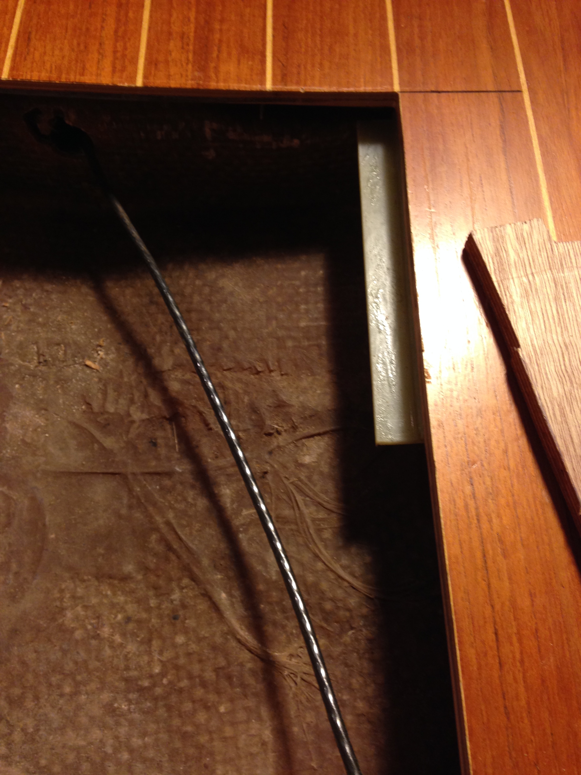
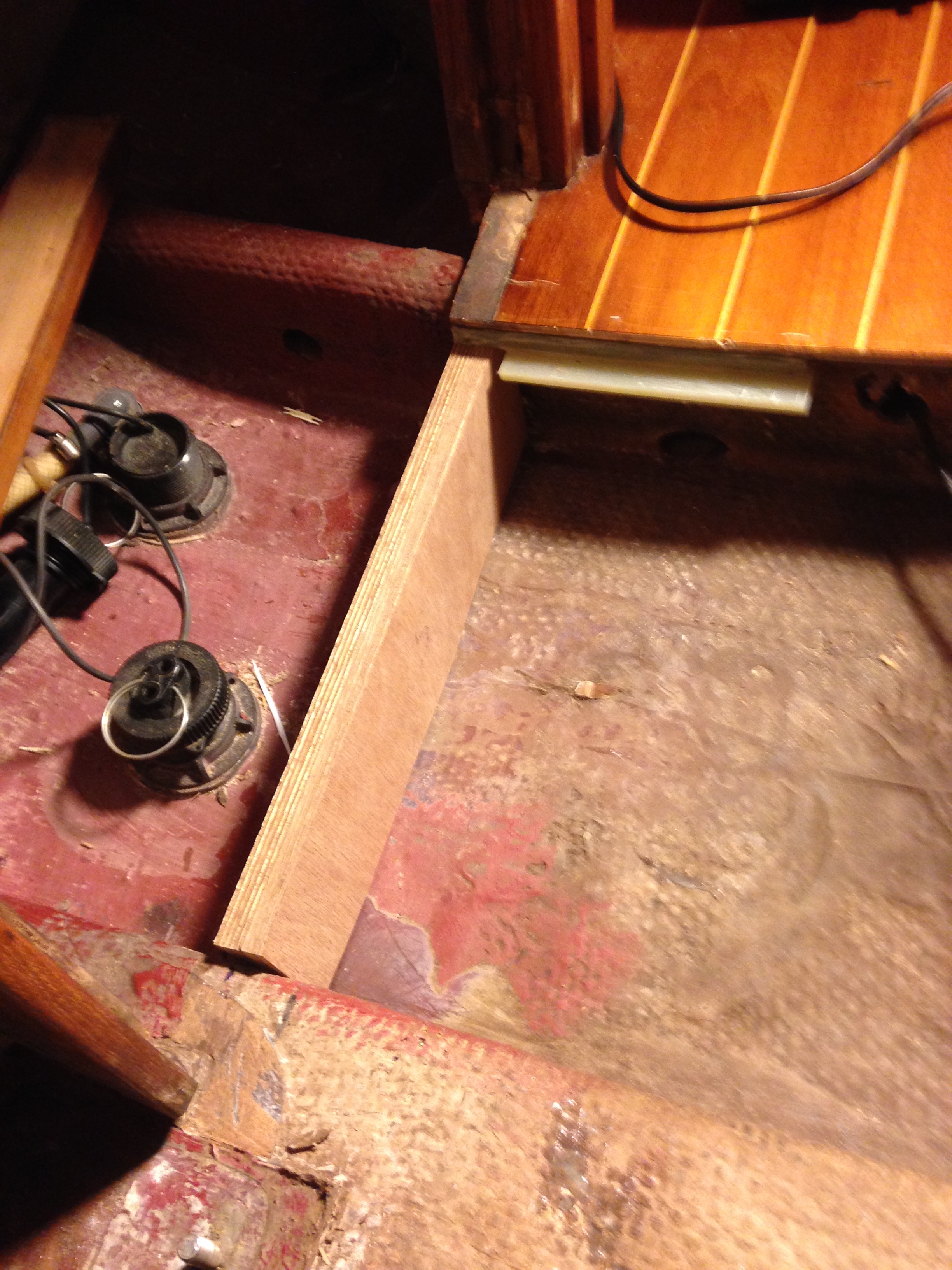
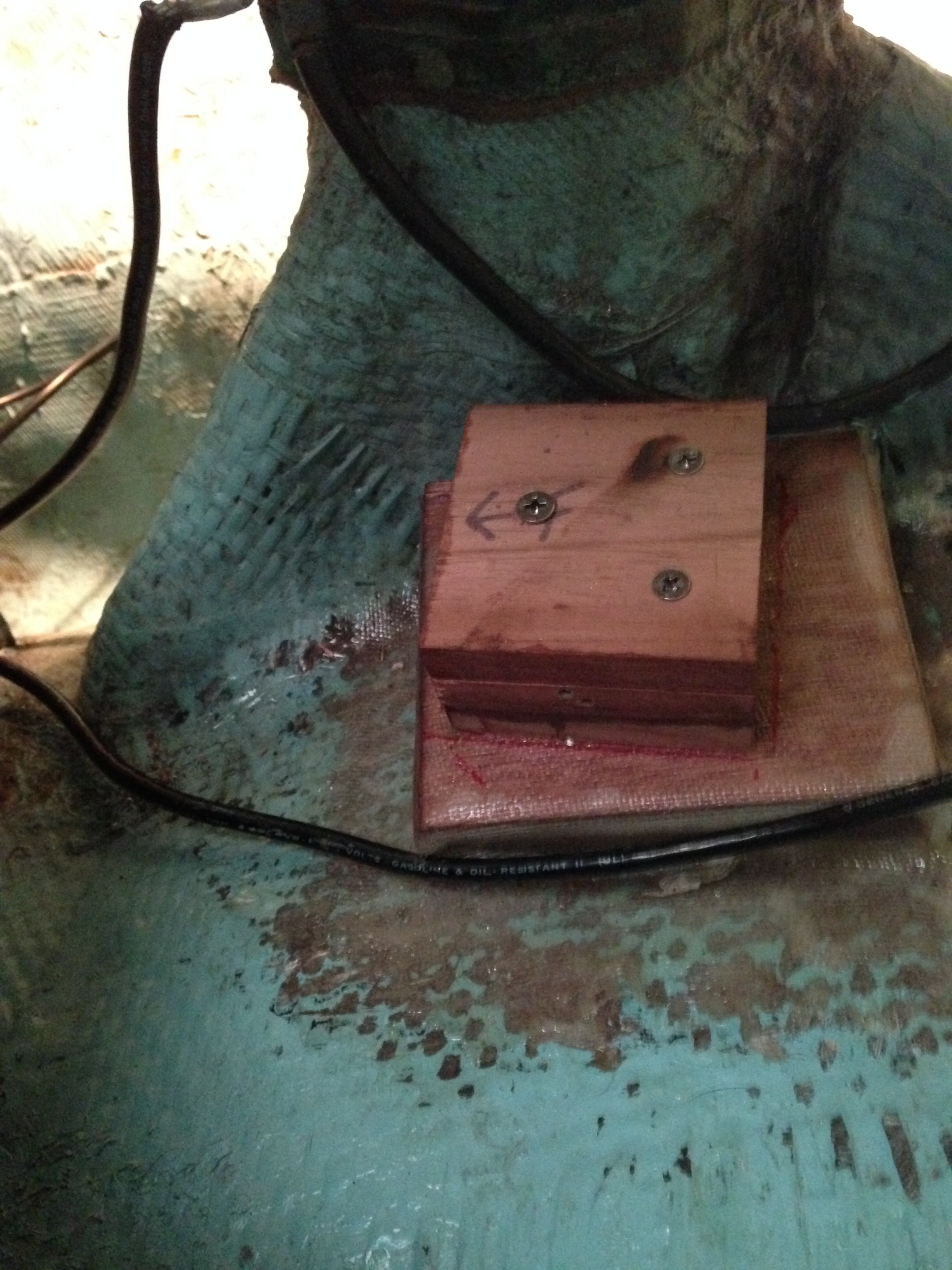
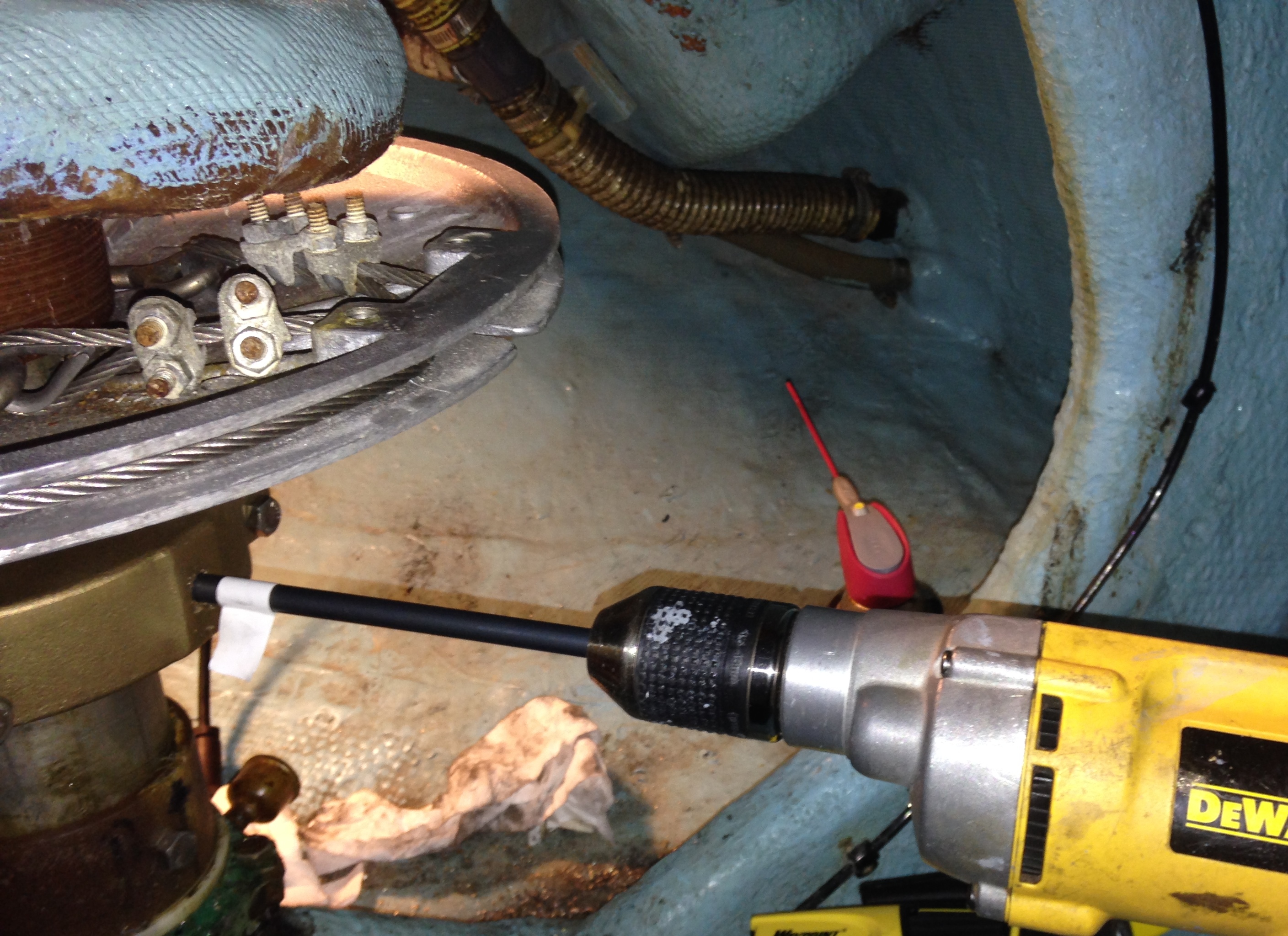
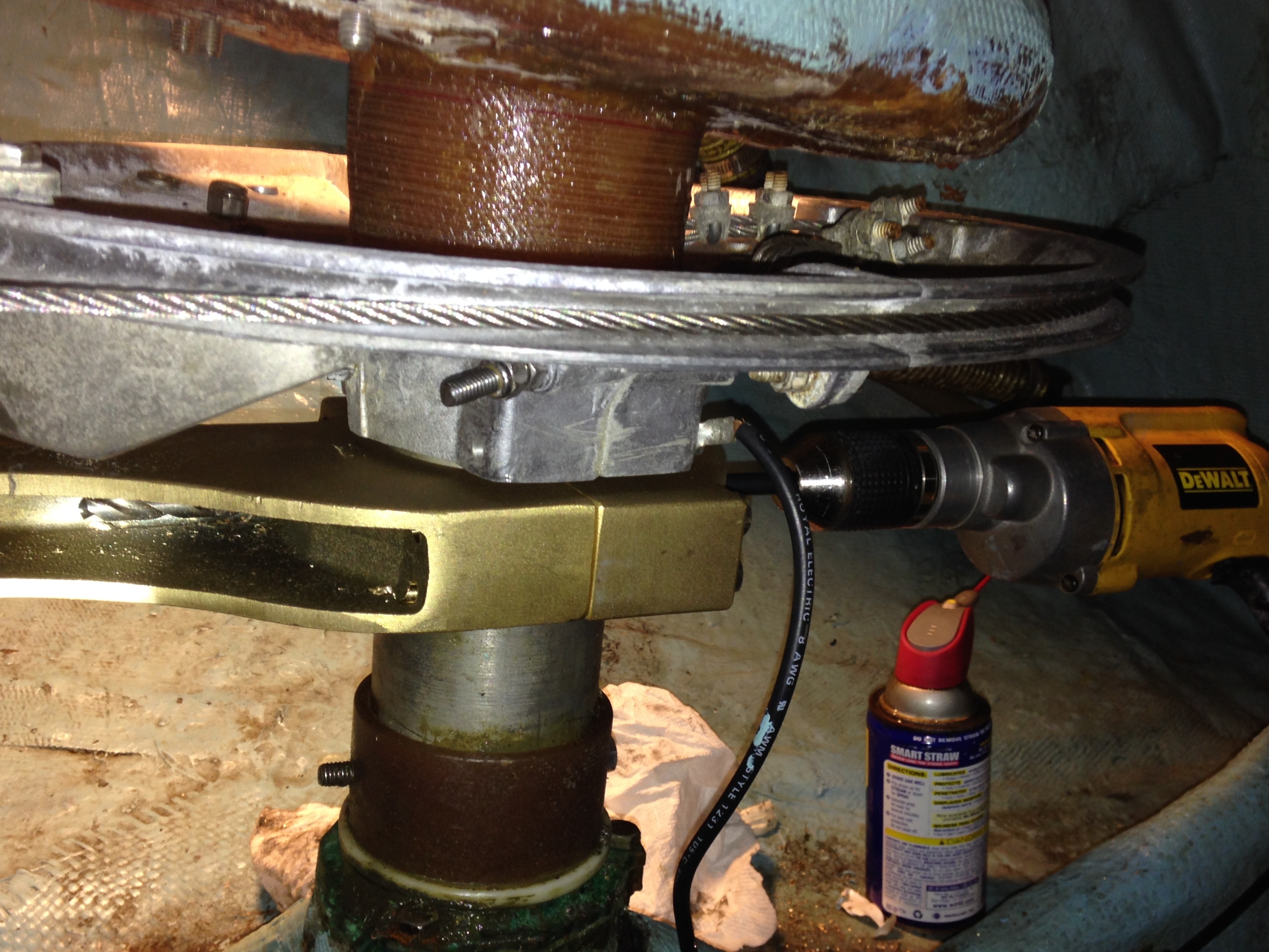
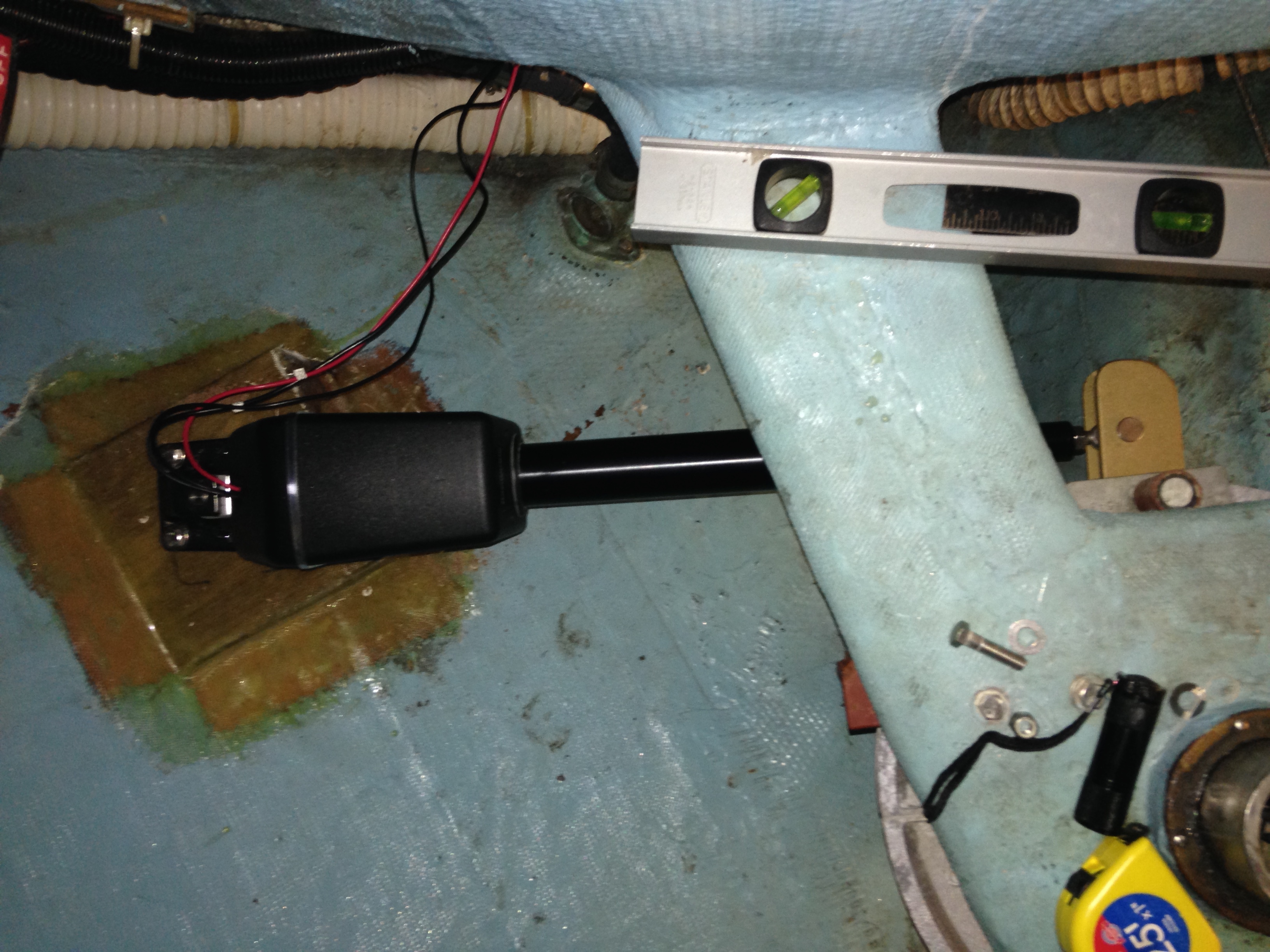
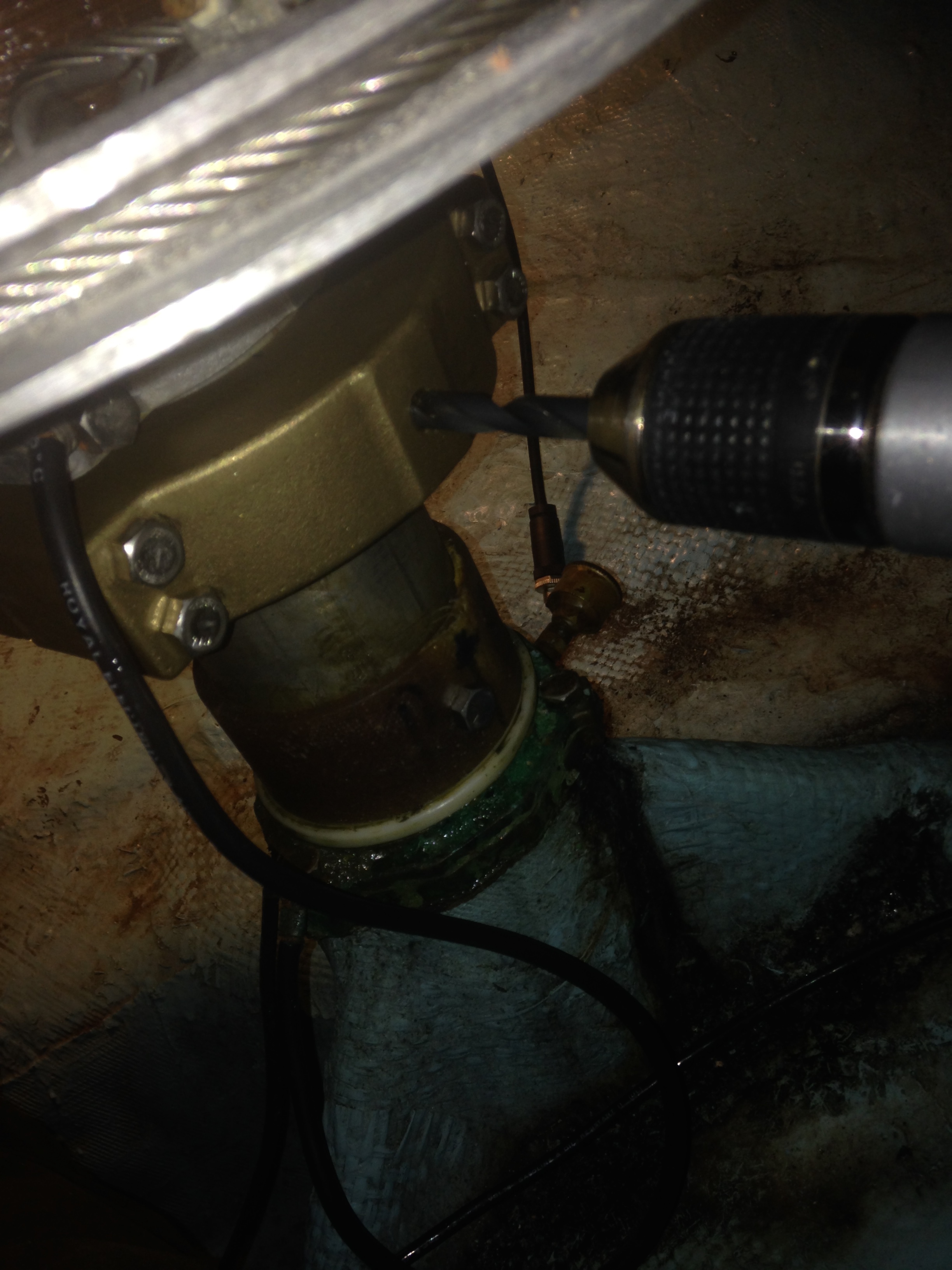
I started by unbolting the mast step casting, then I broke out the multi-master and cut away the rest of the shower support.  I also cut away the bottom some trim around the mast step that was wicking water.  I immediately saw the root cause:  There was a small “channel” in the beam that was funneling water right into the shower support.  This did good as it kept water away from the main cabin sole but after 23 years it finished off the shower support and damaged the cabin sole amidships of the head.

After the support was removed I could lie on the sole and reach my arm underneath to feel the extent of the damage.  Pretty bad right inside the support but drier forward and the main cabin sole was dry as it is seamed at the main beam.  You can see some staining the below picture where some moisture got in the corners.  I got out a straight edge and tape measure and marked the section to remove.  Patience and a multi-master is what is needed for this work.  I experimented with a hand held jig saw and straight edge but the multi-master wins. With practice you get amazing control.

IMG_2049

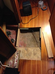
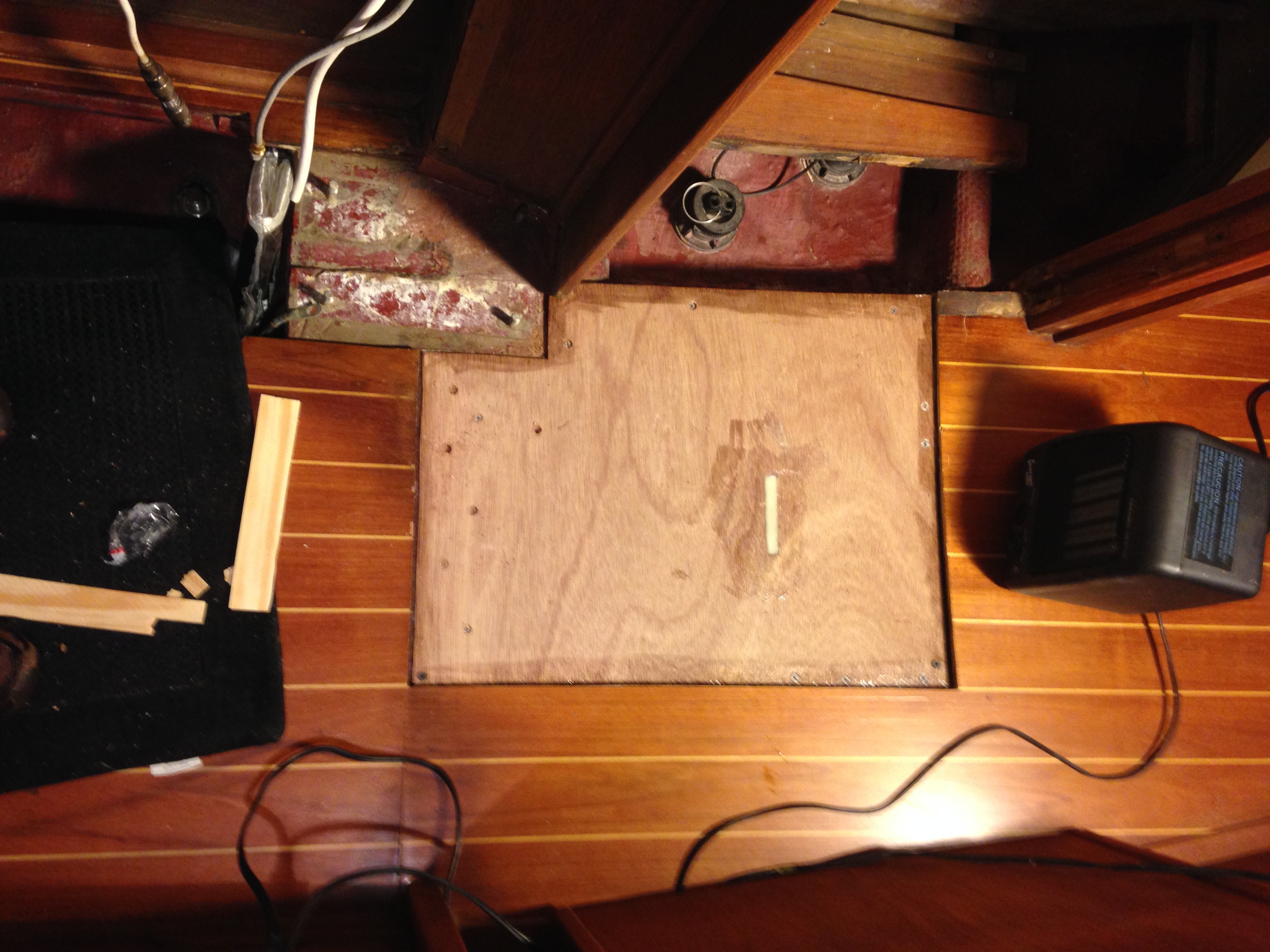
This picture shows the section of sole removed. I was already starting to fit the new shower support and made some brackets to help support the new subfloor. Note the massive main beam that supports the mast.

Next part will cover the fitting of the new shower support and subfloor.

At Dawn on the Sea

I have always enjoyed night passages especially the morning watch.  Seeing the sun come up on the water reminds me of the boundless aspects of sailing a small boat on a big ocean.

Nothing like enjoying a nice cup of coffee while shaking off the night chill as the sun comes up.

Perfect conditions for reflections on life.

5400_97051036148_5114534_n

Unknown tall ship at dawn in the Gulf of Maine 2009

WP_001260

Headed East at dawn

WP_001243

Motoring at dawn in the calm waters of Long Island Sound during an overnight delivery 5/2013

DSC_0365

Morning coffee off Nova Scotia – Marblehead to Halfiax

Below Decks Autopilot DIY Part 3 (of many)

I am making some good progress on the project.  Over the past few days I have the drive aligned and the mounting foot bolted in. I threw together the wiring with temporary rudder sensor configuration and was able to successfully complete the Simrad autopilot installation program and drive test.  Everything is looking good.  Below are some notes for the alignment phase.

Drive Alignment:

The idea is to get things aligned so the drive is at the mid-way point when the rudder is perfectly centered.  Using a tape measure I hand centered the piston.  The Raymarine type 1 has 12″ throw so I set it at 6″ (as close as could).  I also unscrewed the drive end a few turns so it could either way for fine tune adjustment.  I then centered the rudder and noted that my tape mark on the top spoke of the wheel (helm) was centered as well with the spoke perfectly horizontal.

I connected the drive to the tiller arm and set the mounting foot on the base.  Did some alignment checks with a square and level to make sure everything looked ok.  I then drilled two holes through the foot and bolted it down with two SS 3/8 – 16 hex bolts.  I then checked center position by turn the wheel gently to the drive stop port and starboard and using a tape measure to check the height of what was the center spoke above the deck with the goal of identical measurements on either side (~23″ for a Sabre 36 with a 36″ destroyer wheel).  It required some tweaking and I wound up with a second set of mounting holes as I initially had the drive too far towards the center line.

Once I had everything aligned I rigged up the rudder sensor and ran through the calibration and alignment.  This will also show any inconsistencies with alignment.  The rudder sensor calibration should show consistent angles after setting one side.  During the rudder drive test everything sounded nice and smooth.  I then finished bolting down the foot with all four bolts.

During this phase I also measured for rudder bump stop modification.  The stops cannot let the drive exceed it’s limits which is 35 degrees on either side (assuming 10″ radius arm). The Sabre 36 factory setting is around 40+ degrees.  I gently pulled the tiller arm to the drive limit and then measured the gap.  In measuring I found out the  rudder  stop bar was a bit misaligned so one side needs a 5/8″ extension and the other a 3/8″.  I used drill bits like big feeler gauges to help measure  the gap.  I will post some pics of the bar and modifications next post.  I removed the bar to work on it off the boat in the garage.

I had some more time so I started drilling the 3/8″ hole through the rudder shaft and the long side of the tiller arm.  I used smaller bits to drill a pilot hole and it only took about 15 minutes to get through back side.  I am now working with a 10″ 3/8 bit to get through the far side and progress is slower.  I used WD40 as cutting fluid as it is easy to spray into the deep hole with the little straw.

Image

Image

Below Decks Autopilot DIY Part 4 (of many)

Link

Sabre Sailboat Yahoo Group

BTW – For those interested in Sabre Sailboats, please check the yahoo group.  I noticed that yahoo does a terrible job with SEO for their groups and it doesn’t really show up in a Google search for Sabre Sailboats.  There is an active community along with a rich archive of messages, photos and files that covers everything you want to know about Sabre Sailboats.