Project List
This project has many facets. My posts may bounce around a bit but here is the list of specific sub-projects:
- Build/install platform for drive.
- Install tiller arm on rudder shaft
- Align and install drive
- Modify rudder stops for 35 degrees
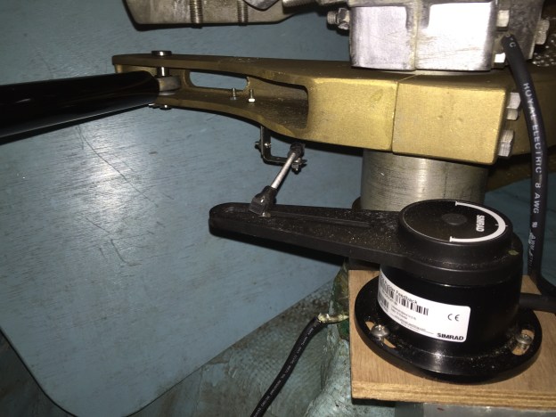
- Install rudder reference sensor
- Install autopilot control head in binnacle pod (will replace old ST4000).
- Install autopilot computer + power
- Install compass
- Wire up everything (head, compass, reference sensor, computer) on the NMEA2000 bus
- Modify below deck steering system cover to fit over ram
This is not a project for the meek. From what I understand pros could charge up to $5K labor for this type of job. There is quite a bit of custom fabrication.
Drive Selection and Installation
If you have a typical quadrant/cable steered boat then you will probably need a linear drive and tiller arm. There are some quadrants designed to have linear drive attached but my Edson quadrant is definitely not one of these. It is aluminum and not designed to be subject to point load forces from a ram.
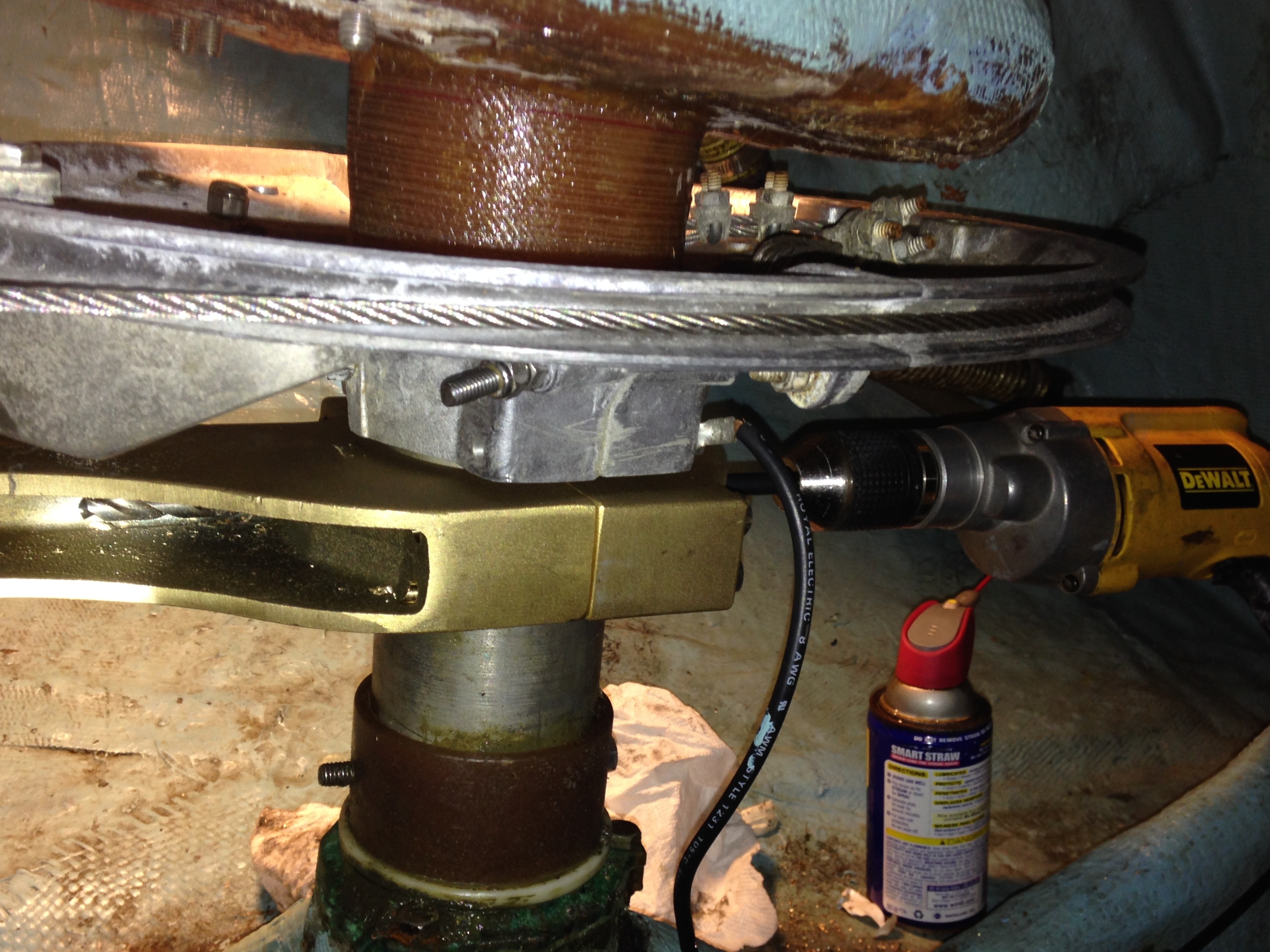
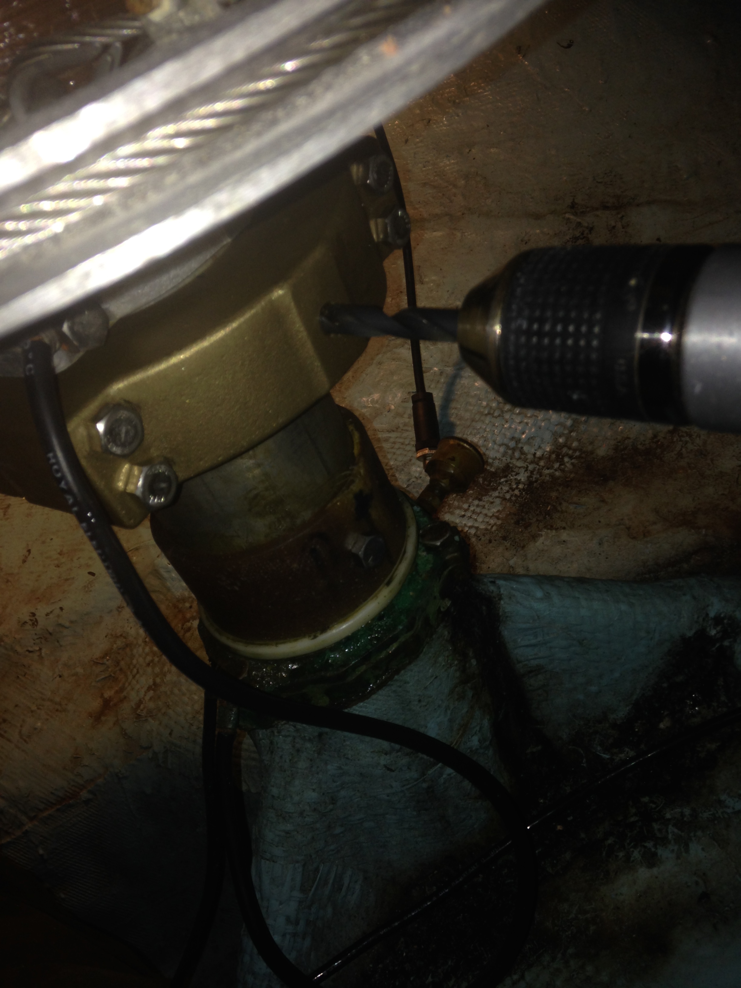
There are a few choices in autopilot tiller arms. I decided to go with the Edson bronze arm. It is not cheap but it is one fine piece of bronze alloy. Edson will custom bore it for the rudder shaft diameter. The Sabre 36 factory spec for my boat is 3.475″. I used a micrometer to double check and found it to be within .003″ at the top so I went with the factory spec. It fits perfectly. Required a twist to work it on and snugs together when the clamp bolts are tightened.

One fine piece of bronze. Took about a week to get from Edson. Because I have hollow rudder shaft and no keyway I went with the through bolt.

Test fit over the top of the rudder shaft. Should be perfectly snug with no gaps when clamp bolts are tightened
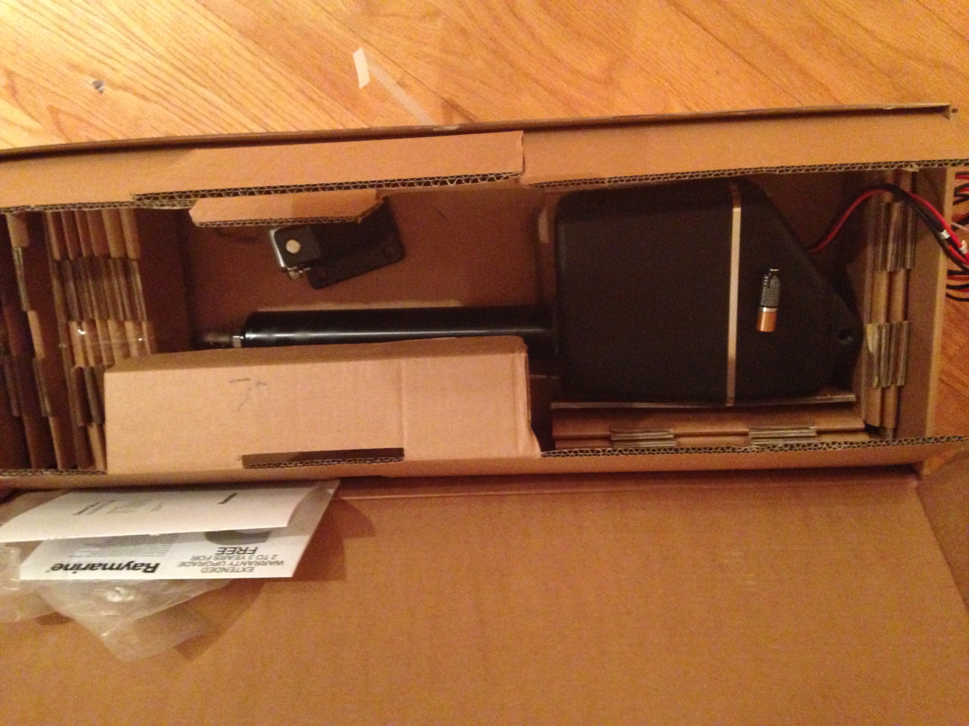
For the linear drive I choose a Raymarine Type 1 Linear drive. When shopping around you have options for hydraulic and mechanical drives. I went with the Raymarine Mechanical for a number of reasons: low power consumption, widespread usage, flexible mounting options and flexible installation tolerances. It also has a decent manual.

Raymarine Type 1 in the box
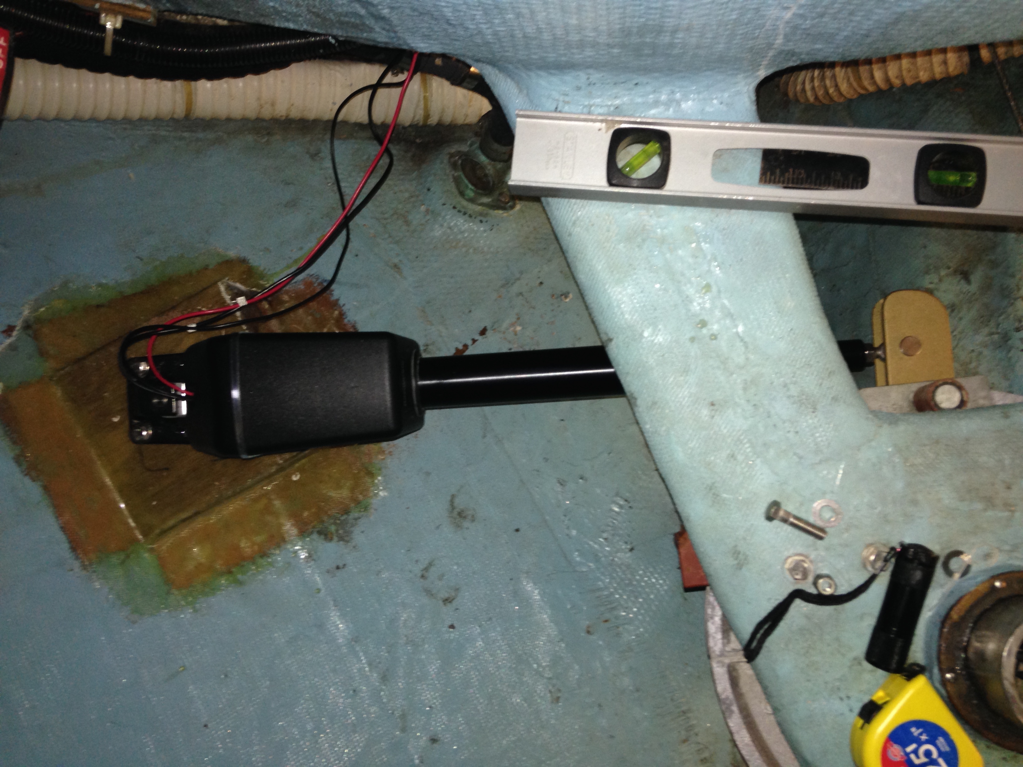
I wanted to tackle the drive install first. The Sabre 36 has a fairly cavernous area aft of the helm. I can lower myself completely into the lazarette and get good access to the rudder shaft and the mounting surfaces. I spent some time in there visualizing the work and decided to install the drive on the port side, perpendicular to the center line. The arm will be installed facing forward. The drive will be mounted to a wedge tabbed into the hull.
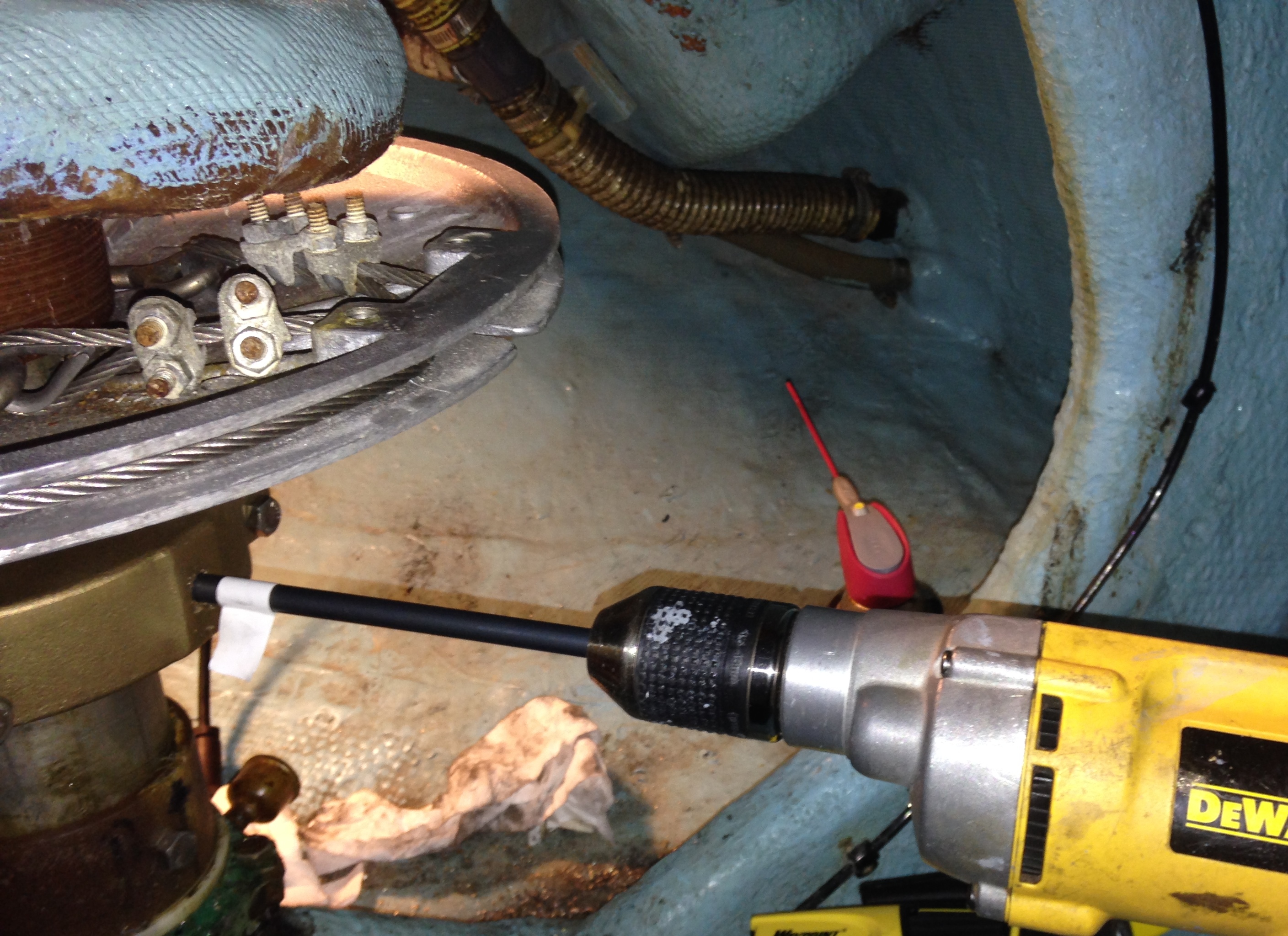
The first step was to attach the tiller arm and get it on centerline. I then clamped a 48″ level to it and worked on determining the wedge location. I accounted for the height difference between the drive mounting foot and drive end using some blocks of wood between the level and arm. For distance I used the mid-position measurement from the drive manual. I used a sharpie to start marking:


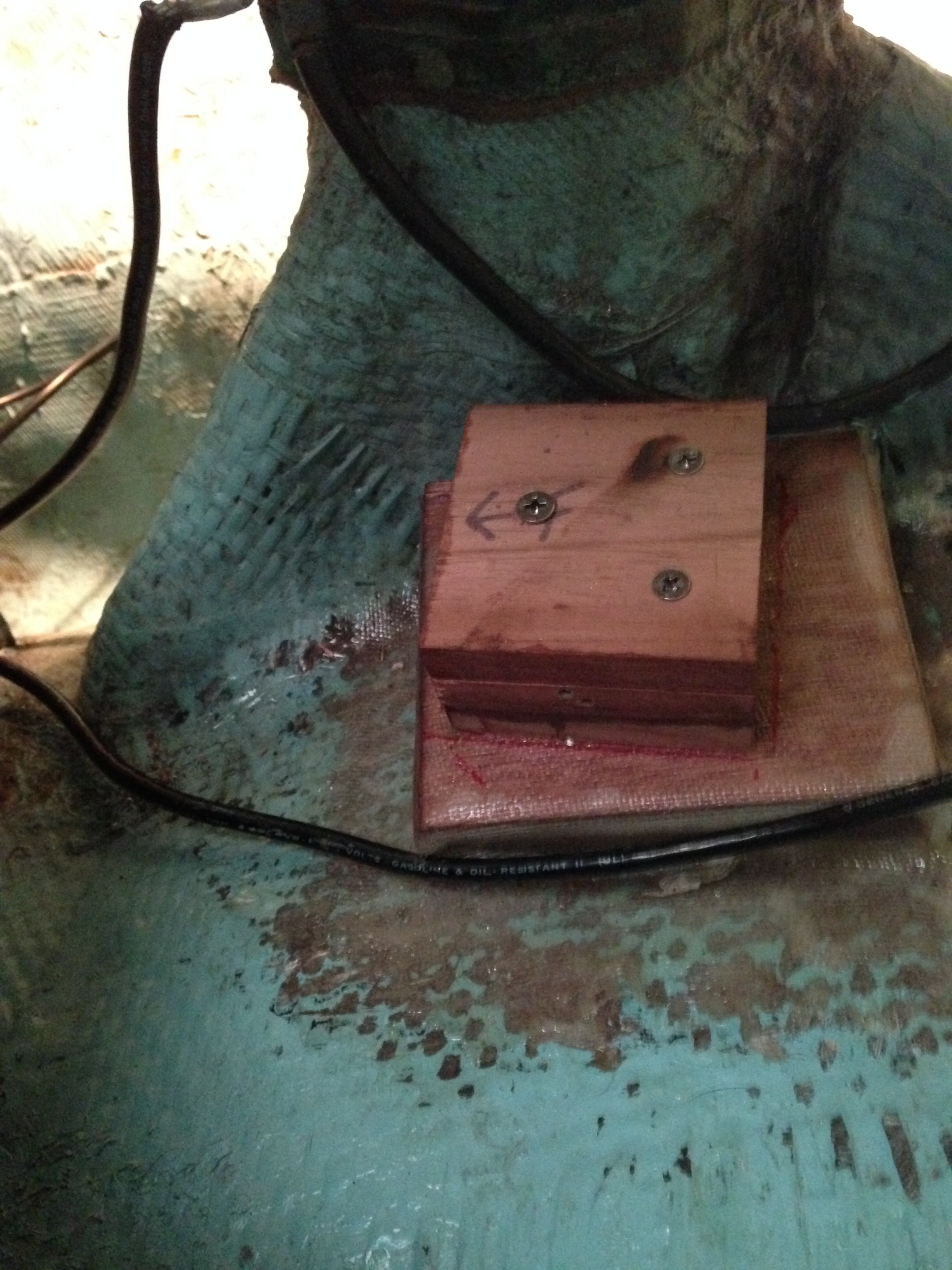
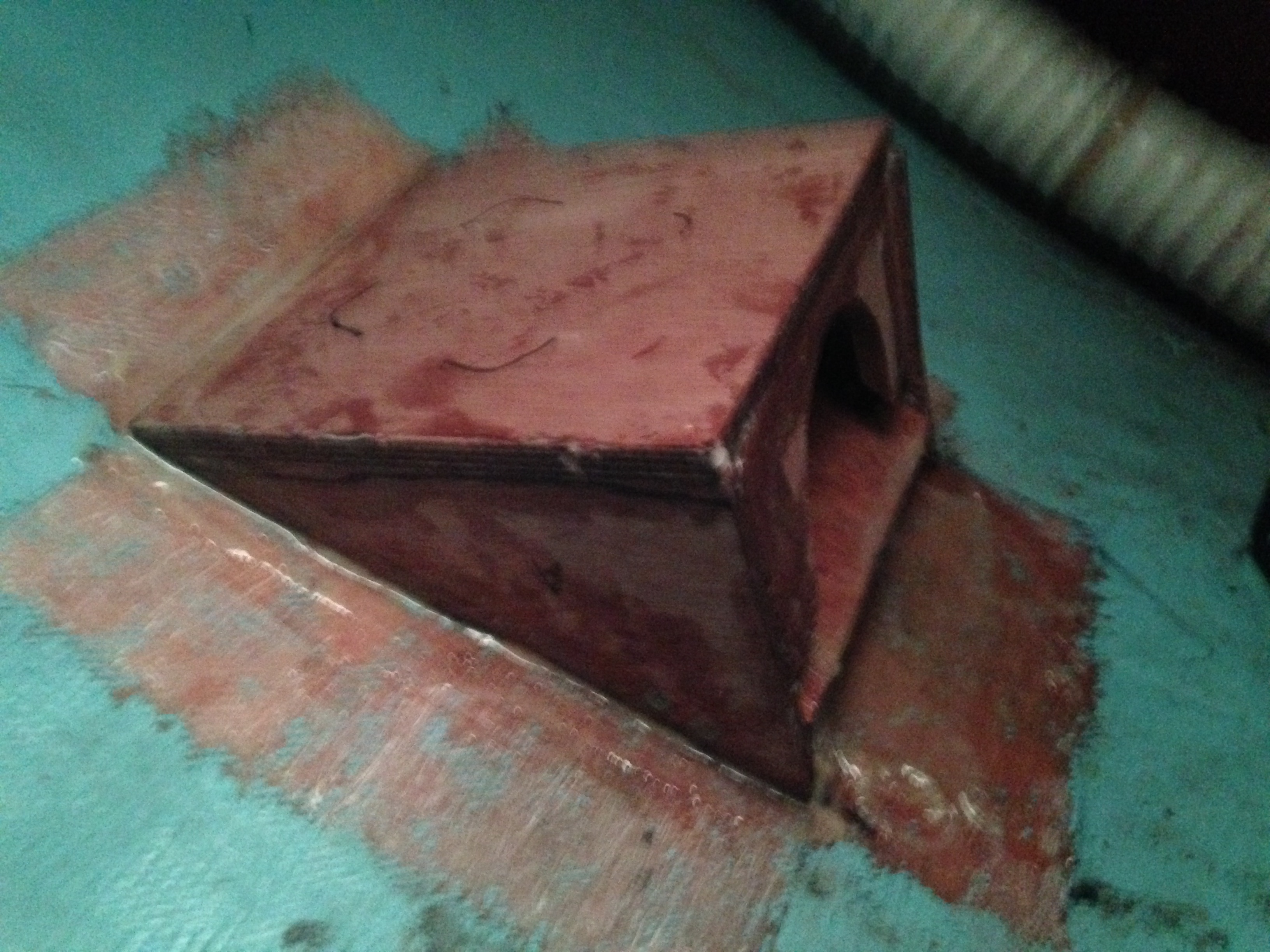
After the measuring was complete. I did some scribing and built a wedge shaped platform using 1/2″ meranti marine ply. This will be built up and tabbed in with west system and glass cloth.

Dry fitting everything

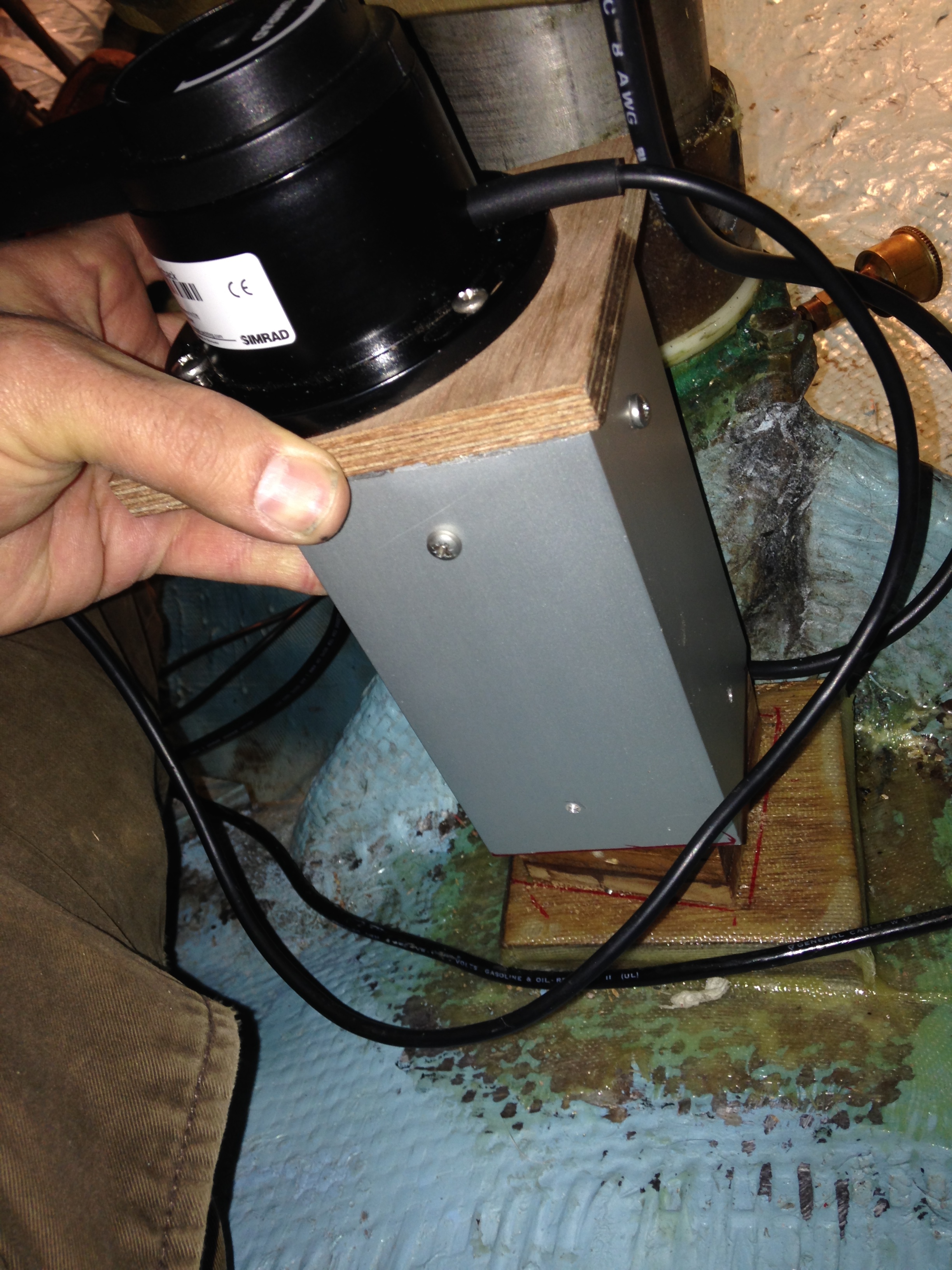
Trying to keep the drive mid-extension for final dry fitting.
Finally I was ready to start thinking about adhesion. I decided first to install a mini-stringer to give the platform more attachment surface and stiffness. The old paint and surface roughed up with a Multi-master and carbide grinding tip.

Stripping paint and roughing up the glass. Using a vacuum to minimize dust in the boat.

Mini stringer epoxied in with first layer of tabbing

Platform bonded to hull plus 4 #10 screws into stringer. More tabbing coming soon. Inside has been stiffened with a layer of cloth and west system before installation.
All bonding with done with West System and High Density bonding filler. All tabbing done with no fillers.
Below Decks Autopilot DIY Part 3 (of many)


")