Tag Archives: install

Autopilot Install Finish

They say better late then never and here it goes.

It has been over two years since I finished the Autopilot install and I couldn’t be happier. The Simrad AC12 steers the boat beautifully and has made cruising a breeze.  Last year we did a two week cruise to Maine with some long delivery days where we barely touched the helm.

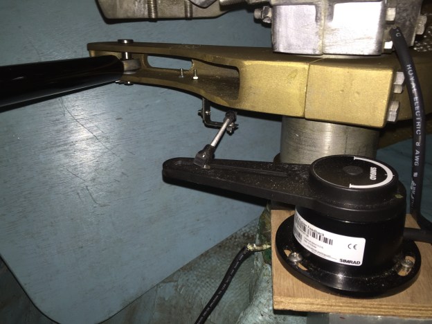
My last entry on the install showed completion of the rudder position sensor.  After the sensor was installed the next step was to get into the wiring.  Using NMEA2000/Simnet on the compass and the rudder sensor simplified the wiring.

The RC42 compass was installed low in the boat, under a settee close to mast.  Basically as close to the center of balance as possible.  This gives the RC42 a truthful picture of how the boat is moving without exaggerations that can cause overcorrections.

I installed the AC12 and wiring hub in the port lazarette on the aftmost bulkhead.  This simplified the wiring as it is just a few feet from the drive and NMEA2000 drops from the rudder sensor, helm mounted chart plotter and Simrad Gs25 mounted on the stern rail.  The AP24 was mounted in an existing pod at the binnacle.  It replaced an old Raymarine st4000 head with a similar cutout size.  I used the old wiring coming out to fish the new wiring coming in.  Using Simnet it was a single wire run.  I also reused the power line from the St4000 as well which speeded up the new wiring install.  The boat already had a dedicated breaker on the main electrical panel for an AP.

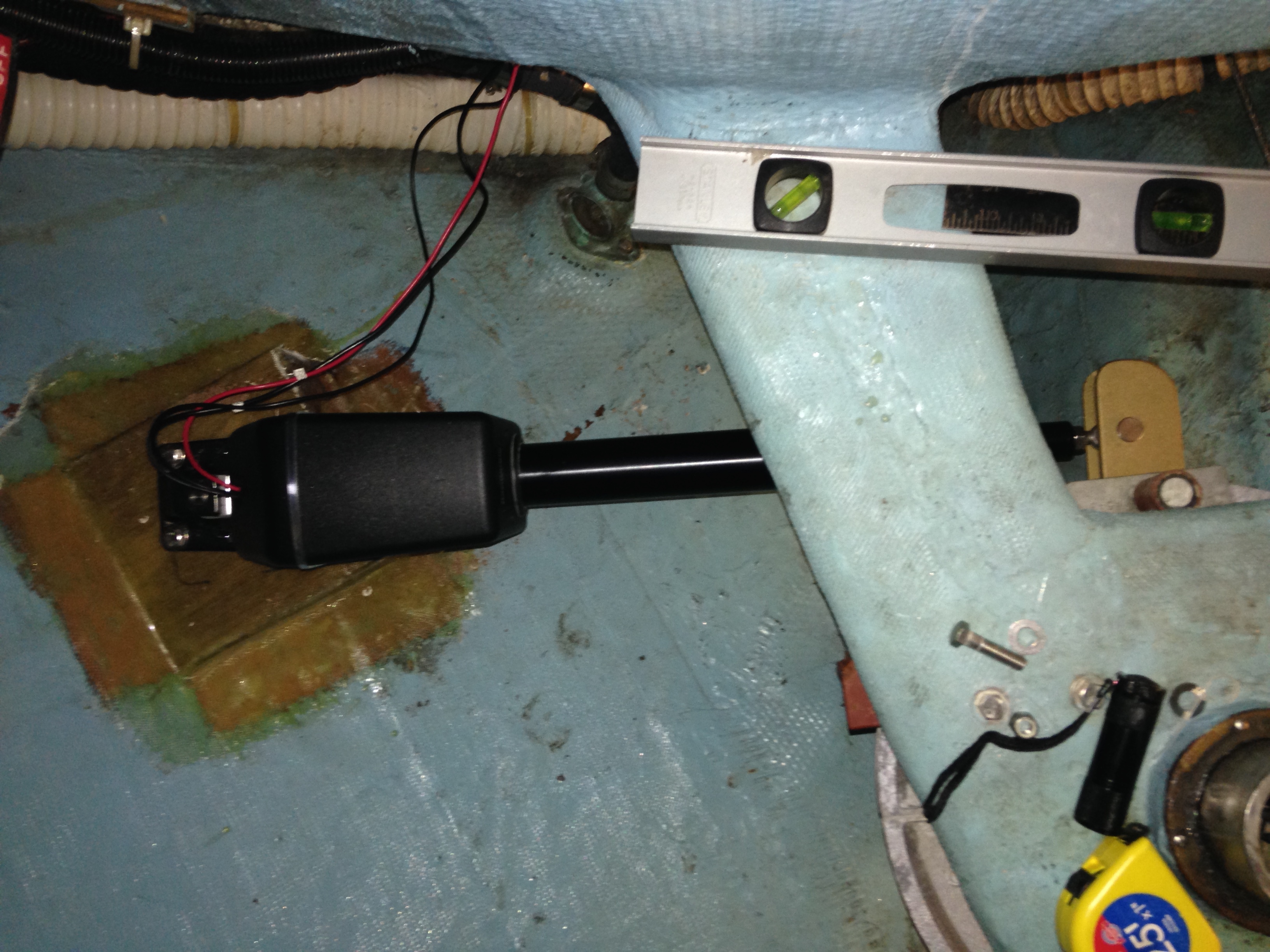
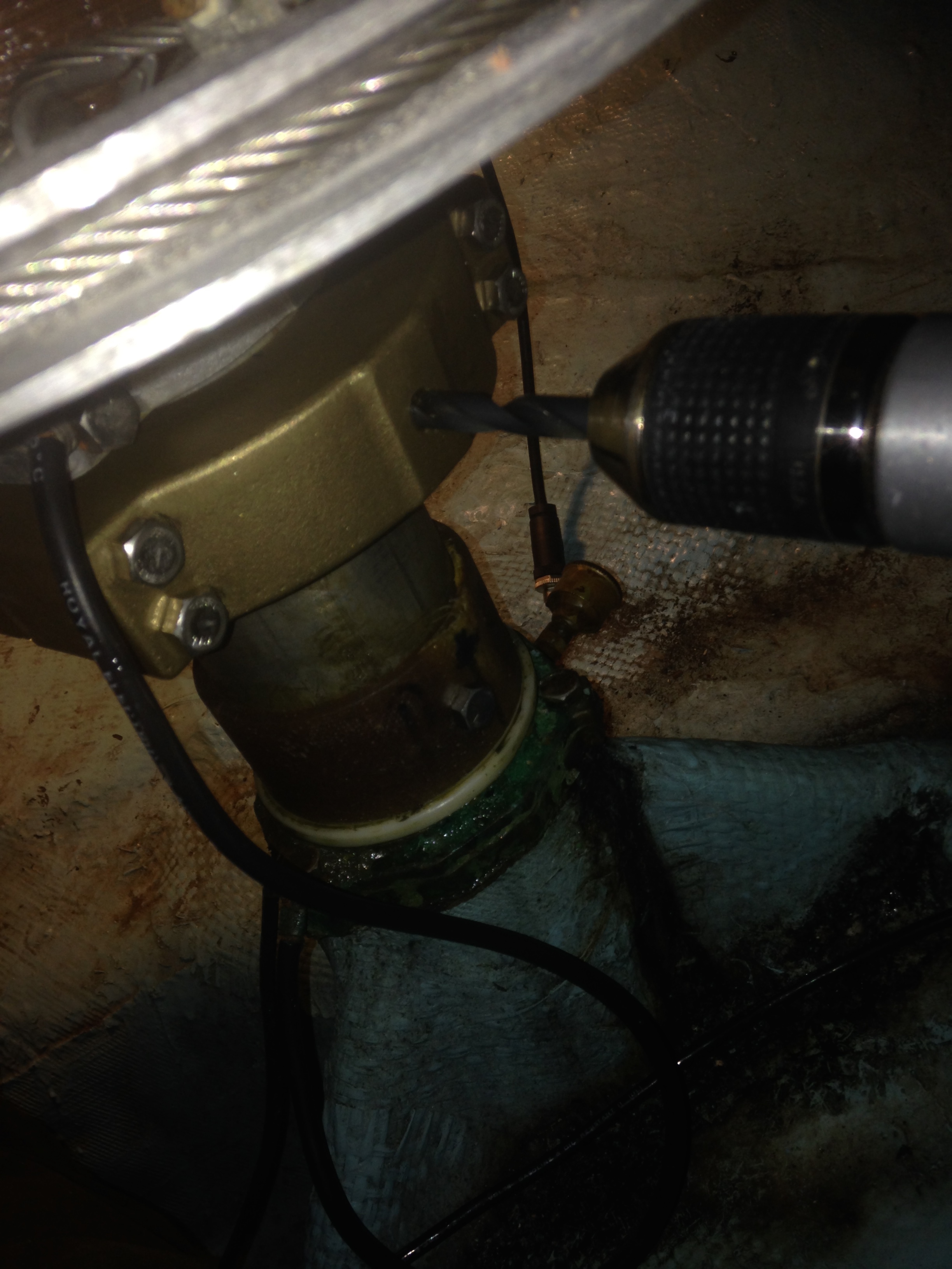
I have had a few comments asking for more photos of the sensor and drive install.  I will try not to disappoint with what is below.  I want to grab a few videos of the AP in action.


Below Decks Autopilot DIY Part 3 (of many)

I am making some good progress on the project.  Over the past few days I have the drive aligned and the mounting foot bolted in. I threw together the wiring with temporary rudder sensor configuration and was able to successfully complete the Simrad autopilot installation program and drive test.  Everything is looking good.  Below are some notes for the alignment phase.

Drive Alignment:

The idea is to get things aligned so the drive is at the mid-way point when the rudder is perfectly centered.  Using a tape measure I hand centered the piston.  The Raymarine type 1 has 12″ throw so I set it at 6″ (as close as could).  I also unscrewed the drive end a few turns so it could either way for fine tune adjustment.  I then centered the rudder and noted that my tape mark on the top spoke of the wheel (helm) was centered as well with the spoke perfectly horizontal.

I connected the drive to the tiller arm and set the mounting foot on the base.  Did some alignment checks with a square and level to make sure everything looked ok.  I then drilled two holes through the foot and bolted it down with two SS 3/8 – 16 hex bolts.  I then checked center position by turn the wheel gently to the drive stop port and starboard and using a tape measure to check the height of what was the center spoke above the deck with the goal of identical measurements on either side (~23″ for a Sabre 36 with a 36″ destroyer wheel).  It required some tweaking and I wound up with a second set of mounting holes as I initially had the drive too far towards the center line.

Once I had everything aligned I rigged up the rudder sensor and ran through the calibration and alignment.  This will also show any inconsistencies with alignment.  The rudder sensor calibration should show consistent angles after setting one side.  During the rudder drive test everything sounded nice and smooth.  I then finished bolting down the foot with all four bolts.

During this phase I also measured for rudder bump stop modification.  The stops cannot let the drive exceed it’s limits which is 35 degrees on either side (assuming 10″ radius arm). The Sabre 36 factory setting is around 40+ degrees.  I gently pulled the tiller arm to the drive limit and then measured the gap.  In measuring I found out the  rudder  stop bar was a bit misaligned so one side needs a 5/8″ extension and the other a 3/8″.  I used drill bits like big feeler gauges to help measure  the gap.  I will post some pics of the bar and modifications next post.  I removed the bar to work on it off the boat in the garage.

I had some more time so I started drilling the 3/8″ hole through the rudder shaft and the long side of the tiller arm.  I used smaller bits to drill a pilot hole and it only took about 15 minutes to get through back side.  I am now working with a 10″ 3/8 bit to get through the far side and progress is slower.  I used WD40 as cutting fluid as it is easy to spray into the deep hole with the little straw.

Image

Image

Below Decks Autopilot DIY Part 4 (of many)